Autonomous Systems: Unmanned Floating Vehicle
Background
The use of unmanned buoys for data collection is not a new concept as government offices such as NOAA utilize them for the collection of weather and oceanic data. The reliability of such systems has been a key focus for development. As of 2020, 10% of NOAA’s buoys have become inoperable. These reliability challenges necessitate the need for an external method of data collection as a portion of the buoys labeled inoperable may have simply experienced a malfunction in their communication systems. As this is the case for simple peacetime equipment, the need for a physical data transfer system is further necessitated by the complexity of wartime systems. An unmanned vessel that is capable of navigating to a buoy, establishing a physical connection, and downloading data would mediate these losses in buoy performance. Furthermore, such buoys could be designed without communication systems which would allow for lower profile designs to reduce the chance of detection while also lowering the procurement costs of these buoy systems.
An existing patent was found for an autonomous vessel. The “Internally Actuated Autonomous Sailing Buoy” was designed as a simple watercraft with the ability to navigate to a preset destination. The design does not include any sensors or data storage systems and incorporates a rudderless design which is made feasible by an internal actuator that controls the sail angle. The design utilizes a sail for propulsion and a moving mass to control the roll of the craft.
Objective
Design a vessel that can be given coordinates of a buoy, autonomously navigate to that buoy and create a physical connection to transfer data. The vessel will then return to the origin of operation for data processing by the Office of Naval Research.
Goals/Requirements
- Autonomous guidance and operation
- Data transfer from the buoy (physical connection)
- Ability to maintain the current position
- Low profile (prevent detection)
- Waterproof housing for electronics
- Low maintenance (renewable power source/minimal moving parts)
- Obstacle avoidance
- Stability in turbulent water/waves
Timeline
Week 2: Introduction to the project
Week 3-7: Investigation into existing designs and preliminary design
Material selection and existing solutions (Weeks 3-4)
Hull design comparison and decision (Week 5)
Design of chassis model and components (Week 6-7)
Finalization of chassis design (Week 8)
Week 8: Summary of chassis results, propulsion design and connection type
Week 9-10: Design of steering system and controller integration
Week 11: Investigation into Expanded Polystyrene performance in water
Week 12-13: Fabrication of chassis
Week 14: Testing of chassis for stability, buoyancy and carrying capacity
Week 15-16: Installation of propulsion and steering system, applicable chassis alterations
Week 17: Final assessment on performance
Week 18: Summary of operational results and documentation
Week 19-20: Preparation for presentation
Innovation & Design Progress
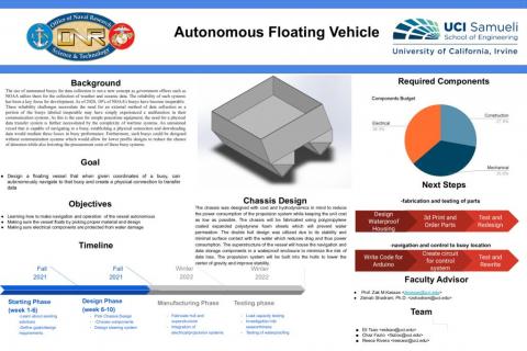
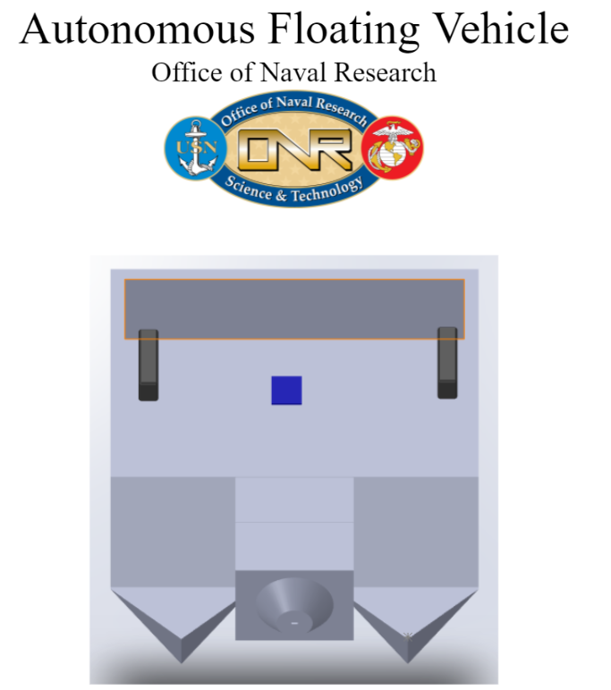
- Structure: The outer frame of the vessel is manufactured from dense styrofoam. This provides an extremely lightweight, buoyant, and water-resistant structure. The chassis serves to securely mount our propulsion and steering mechanisms as well as provide a platform to safely store our electronics within the double-haul structure.
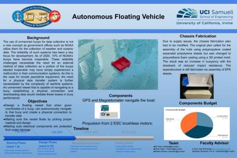
- Navigation: Our navigation system consists of a GPS module and magnetometer as sensors and an Arduino. The magnetometer provides the current direction we are heading in, while the GPS gives longitude and latitude. The Arduino automatically uses this information to calculate how to properly adjust the steering and propulsion to direct the vessel towards the target location.
- Image detection: Once we reach a threshold close enough to the buoy the navigation system switches to image recognition. A pixy camera detects a funnel designated in red color on the buoy. The camera fixes the funnel at the center and continuously tracks it. To ensure a steady connection to the buoy the information from the camera is sent through a PID controller before carefully adjusting the servos and motors to precisely make the connection.
- Micro-Controller: An Arduino Uno board is used to control the vehicle. The board is mounted with an Arduino Motor Shield which serves as an electric speed controller for our motors.
- Movements: Dual 12V DC outboard underwater propellers provide the necessary propulsion for the boat. The steering mechanism of the boat consists of a Servo connected to a rudder at the back of the boat with a wire. The rudder also works in conjunction with the capabilities of dual motors and propulsion steering.
The Bigger Picture
This project was posed by the Naval Surface Warfare Center in Corona and is a chance for the team to engineer a solution to a current real-world problem. The group has met once with Richard Carrasco from the Naval Center, who provided feedback about the existing design and suggested improvements going forward.
Team Contact
Reece Rivera <reecesr@uci.edu>
Chaz Fazio <fazioc@uci.edu>
Eli Tsao <estsao@uci.edu>
Wessam Elmasri <welmasri@uci.edu
Advisor
Dr. Zeinab Shadram <zshadram@uci.edu>
Prof. Zak M. Kassas <zkassas@uci.edu>